I’m pretty new to ham radio, but I always had some passion for antennas, I started when wifi networks appeared on the market, trying to always find ways to get some more signal from the router.
Recently I started to get involved in ham radio, so I started to find antenna projects I can build.
One of the basic building blocks is the so called choke. I encountered it on many antenna builds, so I decided to build one. Here is my experience and my considerations while building it.
First considerations
I started to build a choke as it seems a pretty useful piece of equipment in ham radio, and also because I’m planning to build a MicroVert antenna, and that antenna needs a choke.
A choke is a simple project, and someone just use the feedline wrapped on the toroid, but I preferred to make a box with two female connector so it will be easier to carry or to move it from one antenna to another. I tend to build in a modular way, so I can change elements, remove them, or test them individually. In this way I can use the balun in a new antenna, then just replace the box with a female-female connector and test the same rig without it.
This kind of mentality led me to choose a simple box with two female panel connectors for input/output.
I have a 3D printer, so I used it, but it’s not mandatory, an electrical box could be used instead of the printed box.
Bill of materials
As I said, the balun is pretty simple, a toroid, some cable, two connectors, a box and some zip-ties to fix the coax is probably all you need.
Let’s make the list of what I used:
- Ferrite core – I used a FT-140-43 from aliexpress here.
- RG316 cable – from aliexpress here.
- 2x N Female panel connectors – from aliexpress.
- 3D printed box published by DM4DS, found on thingiverse link.
- 2x small cable ties, I have lots of them, everyone should
You will also need a soldering iron to solder the coax to the connectors, a cutting plier to cut the cable ties and a screwdriver.
The box
The box I used is a 3d Printed one, you can find the project on Thingiverse at this link:
Balun Cases – 1:9 – 1:1 – FT240 – etc.
It’s a project by DM4DS, with various designs and various boxes. I used the one designed for the FT-140 without the central piece and with the holes for the coax connectors.
Assembling the connectors
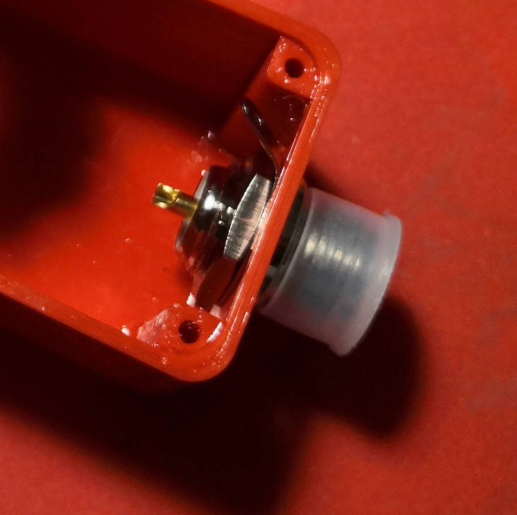
After printing the box I started by assembling the connectors. I used female N panel connectors, the type that screws on the connector body, not the one with four screws, as they seemed easier to install.
While assembling the connector you should position the tab for soldering the coax shield on the upper part so it’s easier to solder instead of having it pointed downwards. Another thing to put your attention to is that the central connector has a cut to help when soldering, you should assemble the connector with the cut on the upper side so it’s easier to reach with the soldering iron.
The winding
The next step is the coax winding on the ferrite core.
I started from one side, leaving a bit more than enough cable to be able to solder both the center and the braid to the connectors.
At the start you can fix the cable with a cable tie, as it’s easier to have it fixed and not unwinding all the time.
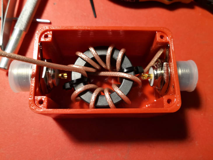
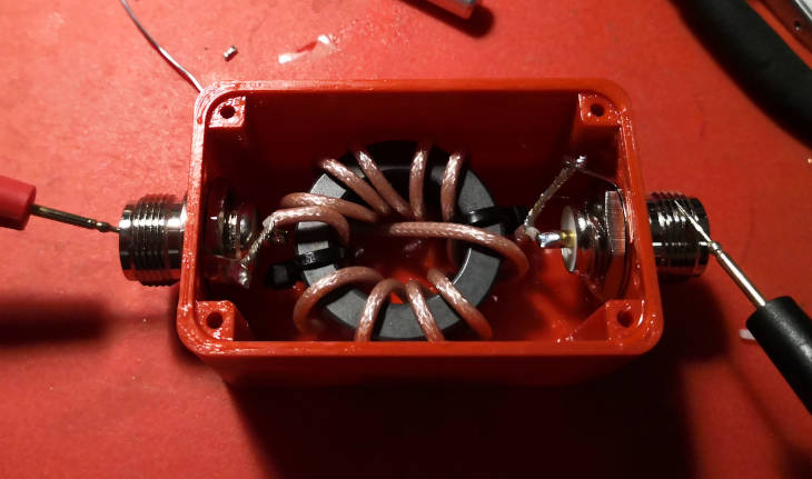
I made 5 turns, then got to the other side by crossing the center and added other 5 turns. Look at the picture for the final result.
The coils should be tight to the ferrite core, but not too tight or there’s the risk of deforming the internal insulator altering the cable’s characteristics.
At the end you can fix everything in place with another cable tie so it will not unwind.
Then I made a test fit to make sure that everything worked and that I had enough cable to make the connections.
Soldering the coil in place
The next step is soldering the cable to the connectors.
To do this I started by stripping the cable from the external. Here it’s important to not strip too much, as you should avoid contact between the cable and the coil.
With the connectors I used I think the space between the coil and the connector got a little tighter, as they are a little bulkier than the flange type ones. To avoid touching the ferrite and stripping too much insulator, I did it in incremental steps. I test fitted the coil in the box, took the measure and stripped a little less cable, then test fitted again, and stripped the other part after checking again.
Then I wrapped the coax braid on the side where the ground tab of the connector was installed, test fitted the coil again making sure that I had enough braid to reach the tab.
After the braid I stripped the central insulator, you should leave a little insulator exceeding from the braid, so the braid will not short to the center conductor.
This should be the final result.
Then it’s time to heat up your soldering iron and start soldering everything together.
To avoid doing it in an uncomfortable position, you can tin the wires with the soldering iron, so that once in place it will be easier to solder them.
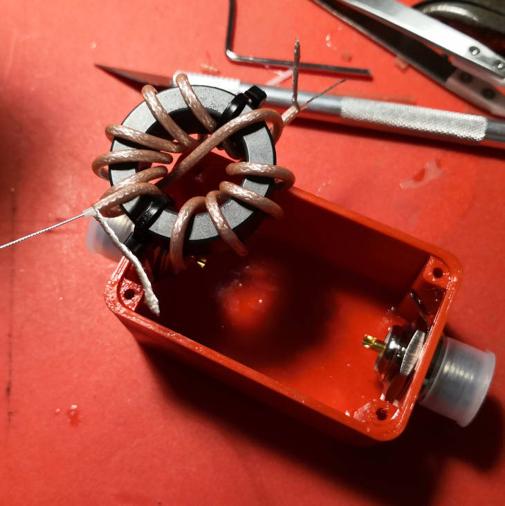
I started by fitting the coil inside the box, trying to leave equal spacing between it and the connectors.
I then started to cut the excess wires. I started from the less comfortable side, the one with the cable coming from below the coil. Tested the position of the central wire, then cut it. Then soldered and made the same for the braid.
Once the less comfortable side is soldered, it could be time for a first continuity/shorts check. If you don’t have a multimeter you can jump this step, but a multimeter is a great tool to have, even a cheap one is ok to check continuity and will save you headaches if there’s something wrong. If you have a multimeter, then take the 30 seconds this step requires and make the check.
With the multimeter set to continuity check that the center of the soldered connector is actually connected with the center wire on the other side of the coil, and the outer part of the connector is connected to the braid on the other side. you should also check that the center wire and the braid are not shorted together. If they are, you should stop, find where the two are shorted and fix the issue.
When soldering always remember that heating too much could damage the central insulator with the risk of shorting together the wires (you will notice this when testing for shorts with the multimeter)
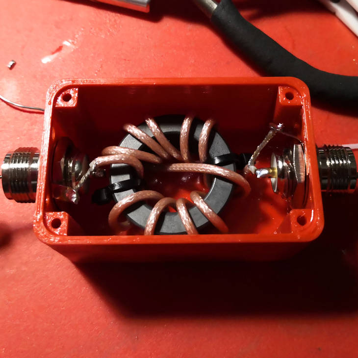
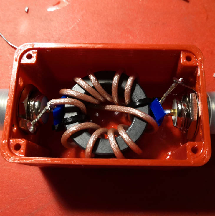
Once tested the first soldering, I proceeded soldering the other connector using the same approach.
The final result should be something like this:
The work is almost over, now it’s again time for testing.
Continuity test
Again this is a frequently skipped step, but you shouldn’t skip it, as the earlier you find an issue, the less you will worry about what is causing it. If you skip this and start using your balun with a short or with an unconnected wire, your radio will not work, you even risk damaging it, and you will have less clues about what’s not working (the radio? the antenna? the cable? the balun?). So take 2 minutes now with your multimeter and be sure that at least everything is connected where it should be.
Again the checks are the same as in the previous step. You should check that:
- The center pin is isolated from the outer part of the connector.
- The center pin on one side has continuity (is connected) to the center pin on the other side.
- The outer part on one side has continuity with the outer part on the other side
As I was pretty worried about the center pin of the connectors touching the ferrite I added two scrap 3d printed pieces between the connector and the ferrite. This can be also done with some insulating tape or some other insulating material.
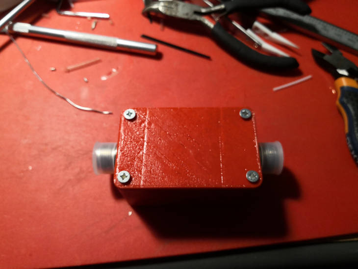
We got to the end: now we just have to put the lid and screw it together.
The result will be a compact box with two connectors you can easily plug and unplug to test various configurations.
As I said I’m pretty new to ham radio, so if you find something wrong with my choke balun construction please leave a comment below.